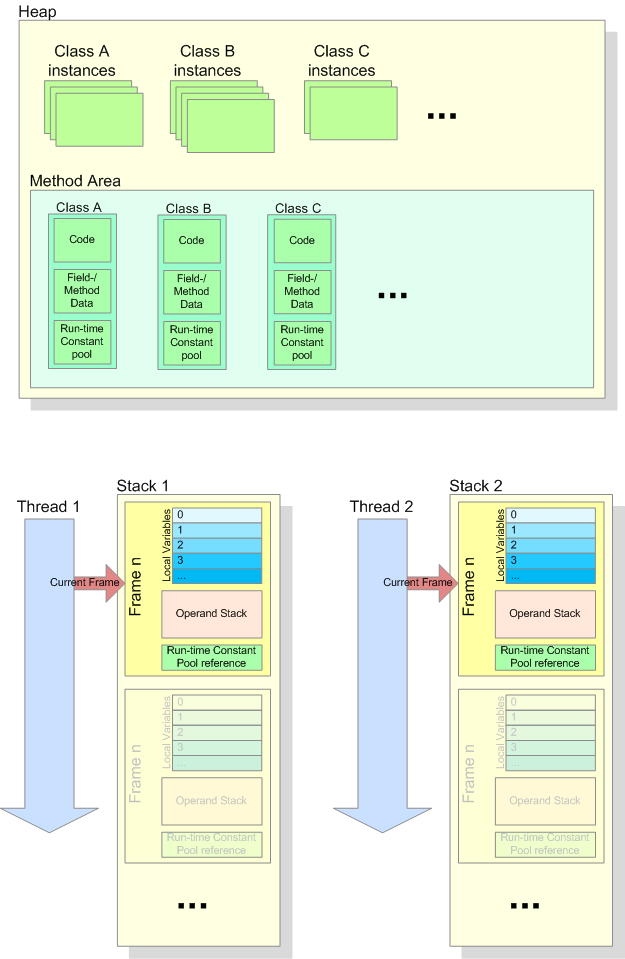
The following diagram summarizes the internal structure of a Java Virtual Machine’s memory structure as specified in chapter “2.5. Run-Time Data Areas” in The Java® Virtual Machine Specification, Java SE 8 Edition. In this example, three classes A, B, and C have been loaded into the JVM, and for each of those classes, a varying number of instances have been created. Two threads have also been created.
The Frames on each Thread’s stack are associated with a particular method. Each time a method is invoked, a new Frame is created on the Stack. When the method returns, the frame is discarded from the stack. The Frame which is associated to the current method is the Current Frame. Each Frame has an Operand Stack which is used by the bytecode instructions to perform operations. Local variables are referenced by their index, starting at 0. The Runtime Constant Pool reference in each Frame is a reference to the Runtime Constant Pool of the class which contains the method which is currently executing.
Suppose you have an Image and want to extract the color channels for red, green and blue into three new images. A straight forward way would be to create a new empty image with the same size as the source image, iterate the source image pixel by pixel, convert the pixel color of each pixel and set the converted color for each pixel in the destination image. In JavaFX, this is possible through the PixelReader and PixelWriter interfaces:
public Image getBlueChannel(Image sourceImage) {
    PixelReader pr = sourceImage.getPixelReader();
    int width = (int) sourceImage.getWidth();
    int height = (int) sourceImage.getHeight();

    WritableImage result = new WritableImage(width, height);
    PixelWriter pw = result.getPixelWriter();
    for (int x = 0;  x < width;  x++) {
        for (int y = 0; y < height;  y++) {
            Color col = pr.getColor(x, y);
            pw.setColor(x, y, new Color(0, 0, col.getBlue(), 1.0));
        }
    }

    return result;
}
This example creates a new WritableImage with the same size as the source image, and then iterates the source image pixel by pixel and sets the corresponding pixel in the writable image, using the blue component of the source pixel only.
While this works well (and shows how to access individual pixels of an Image, which can be useful in various situations) it is definitely not a good approach, especially due to performance reasons. It might work well enough for a smaller image (like 200×100 pixels) but for larger images it will most likely get too slow.
A much better way is to use the JavaFX Blend effect which takes two input sources and combines them into an output. The two input sources are called topSource and bottomSource, and they can be combined by a couple of operations which define how each individual pixel of the two input sources are combined to create the result pixel. When the effect is applied to a node in a scene graph, the node itself is taken as top source and/or bottom source if either of them has not been set explicitly. Thus, if the top source is explicitly set for the Blend effect and then the effect is applied to a node, the result is the topSource combined with the node itself. The following example creates a ColorInput where all pixels are set to blue (rgb(0, 0, 255)) as the top source, and an ImageView node is used as the bottom source. The two sources are combined by multiplying the color values of each pixel to generate the resulting pixel:
public Image getBlueChannel(Image sourceImage) {
    ColorInput colorInput = new ColorInput();
    colorInput.setPaint(Color.Blue);
    colorInput.setX(0);
    colorInput.setY(0);
    colorInput.setWidth(sourceImage.getWidth());
    colorInput.setHeight(sourceImage.getHeight());

    Blend blend = new Blend();
    blend.setMode(BlendMode.MULTIPLY);
    blend.setTopInput(mask);

    Node img = new ImageView(sourceImage);
    img.setEffect(blend);

    SnapshotParameters params = new SnapshotParameters();
    Image result = img.snapshot(params, null);

    return result;
}
Why does the example use the MULTIPLY operation for each pixel? In the earlier days, a 24 bit RGB pixel was made up of three eight-bit-values, one for each color channel:
   Red         Green        Blue
xxxx xxxx    xxxx xxxx    xxxx xxxx
So, to get one of the color components only (say, blue) it sufficient to create a bit mask where only the bits from the blue channel were set to 1. By AND-combining the color with the mask, the blue channel was then extracted:
       Red         Green        Blue
    xxxx xxxx    xxxx xxxx    xxxx xxxx
AND 0000 0000    0000 0000    1111 1111
----------------------------------------
  = 0000 0000    0000 0000    xxxx xxxx
In JavaFX, the color channel values are floting point values between 0.0 and 1.0. In order to keep the values for one color channel and set the values for all other color channels to 0.0, we can multiply the color with (0.0, 0.0, 1.0):
    Red   Green  Blue
    n.n    n.n    n.n
X   0.0    0.0    1.0
----------------------
=   0.0    0.0    n.n
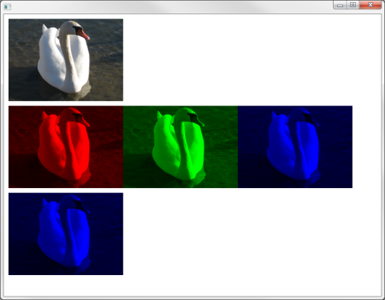
The lower blue image uses the initial example where each individual pixel is processed through a PixelReader and PixelWriter.
Alternative approach
If we only want to display the color channel of the image, and if there is no need to further process the images which contain a specific color channel, we do not need to generate real Image instances for each color. We can simply use different ImageView nodes which all use the same source image, and apply the Blend effect for red, green and blue to the ImageView nodes:
    ...
    // Create Blend effect for red channel
    ColorInput colorInput = new ColorInput();
    colorInput.setPaint(Color.RED);
    colorInput.setX(0);
    colorInput.setY(0);
    colorInput.setWidth(sampleImage.getWidth());
    colorInput.setHeight(sampleImage.getHeight());
    Blend redBlend = new Blend();
    blend.setMode(BlendMode.MULTIPLY);
    blend.setTopInput(mask);

    // Create Blend effect for green channel
    Blend greenBlend = ...

    // Create Blend effect for blue channel
    Blend blueBlend = ...

    ImageView sourceView = new ImageView(sampleImage);

    ImageView redView =   new ImageView(sampleImage);
    redView.setEffect(redBlend);

    ImageView greenView =   new ImageView(sampleImage);
    greenView.setEffect(greenBlend);

    ImageView blueView =   new ImageView(sampleImage);
    blueView.setEffect(blueBlend);
    ...
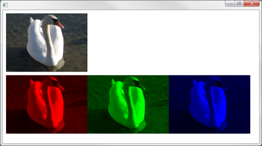
The result is the same as above, but we did not have to create all the Image instances:
While playing around with Borders in JavaFX, I came across the term “9-patch scaling technique”, and I wondered what that actually means.#
First of all, “9-patch” means that a rectangular area is divided into 9 areas (patches) of possibly different sizes as shown in the following image:
Each area has either a fixed size (the corner areas 1, 3, 7, 9), or it can be resized vertically (4,6) or horizontally only (2,8), or it can be resized both vertially and horizontally (the central area, 5).
When using “9-patch scaling”, each area gets a particular fill color, pattern or even image assigned. If a pattern or image is used, it is either stretched or tiled (repeated) in those areas which are resizable, so that the pattern or image fills the whole area.
Normally, the central area contains some particular content, and the outer areas are used to define a border around that content. In JavaFX, the rectangular area itself is a Region or one of its sub classes, and its Border can be set with the Region.setBorder(Border value) method.
Border is essentially a list of strokes and images which are drawn one above the other, in the order they are stored in the list. There are some special conditions to consider especially when using both Strokes and Images with the same Border. The remaining article will focus on using images, hence I will not go into the details of these constraints. See https://docs.oracle.com/javase/8/javafx/api/javafx/scene/layout/Border.html for more information.
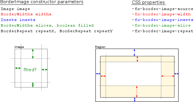
Image based borders can be created either in code through the BorderImage class, or they can be defined in CSS. The following diagram shows the BorderImage parameters, their corresponding style sheet property and how the given values are used to specify the border:
The image itself is defined through the Image parameter or through the -fx-border-image-source CSS property. The slices parameter or the -fx-border-image-slice property defines the slices on the source image. The filled parameter specified whether the central slice should also be used when rendering the border – in CSS, this is part of the -fx-border-image-slice property by adding a value of fill.
The remaining parameters define how the border is constructed – the widths parameter or the -fx-border-image-width CSS property (shown in red above) defines the width for each of the four border edges. Note that its also possible to specify one value only (the BorderWidths constructor has a single argument variant) – in that case the value applies to all four edges. The insets parameter or the -fx-border-image-insets property (shown in blue above) defines the distance from the Region’s bounding box to the border. Finally, the repeatX/repeatY parameters or the -fx-border-image-repeat property defines how the slices in the border are filled if the corresponding image slice is too small – essentially, the image can be repeated (tiled) or scaled (stretched).
As an example, lets assume that we have a simple Button which we would like to surround with a border:
The button is created in Java code like this:
Region r = new Button("Hello World");
r.setId("hello");
To add the border, we need to create an image (lets call it border.png) similar to the following one:
How exactly the image looks like and how large it is is of secondary interest – we could even discard the central white rectangle, since we define the area to use from that image through the slice property. It is just important that the image can be divided into nine areas when applying the sizes given in the slice parameter:
Some more advanced examples are shown at https://www.w3.org/TR/css3-background/#border-images. As the next step, we might want to try to add an additional image like a status indicator to the border. Lets assume that we have the following image trafficlight.png which we would like to add to the upper right corner:
In theory, this is possible since we can define a list of images and/or strokes when specifying the border. In CSS, this is done by specifying the parameters for each image separated by commas:
In order to see the whole image unscaled, we set the top and right slice to the image’s size, and we also specify the corresponding border widths with the same size. This results in the following image:
As you see, the right border now has the width of 46 pixels as specified – depending on the use case, this might work well but probably the expectation was to achieve something like this:
We could try to put the traffic light into the top slice instead of the top right slice, but as said above the slices are always fillled, either by stretching or by repeating the corresponding image slice (the CSS value no-repeat is actually “stretch”):
Again, depending on the use case, this might be usable, and if it is assured that the central area always has the same width (which often is not the case) one could use a larger source image which fills the whole border in order to avoid scaling/stretching. However, a better solution in this case is to use a layout component like BorderPane and not use borders for such use cases.
In Eclipse, it is possible to log particular expressions like the current value of a method parameter to the console during a debug session, without the need to continously press the “resume” button . Lets assume we have the following code which does some calculations:
package com.example;

public class DebugSample {

    private double calculate(double input) {
        return Math.sin(input * input);
    }

    private void processValue(double value) {
        // ...
    }

    private void run() {
        double value = 0.0;
        while(value < 20) {
            double newValue = calculate(value);
            processValue(newValue); // do some processing with the calculated value
            value = value + 0.5;
        }
    }

    public static void main(String[] args) {
        new DebugSample().run();
    }
}
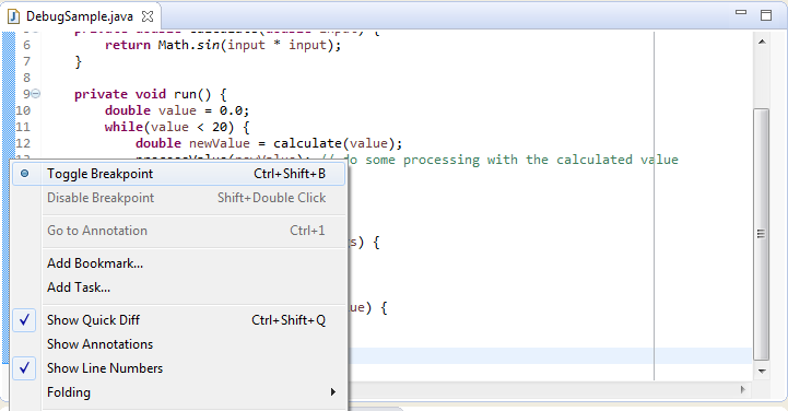
Now, if we want to check the contents of the calculated value (newValue) inside the while loop, we can simply set a breakpoint at the line after the call to the calculate() method:
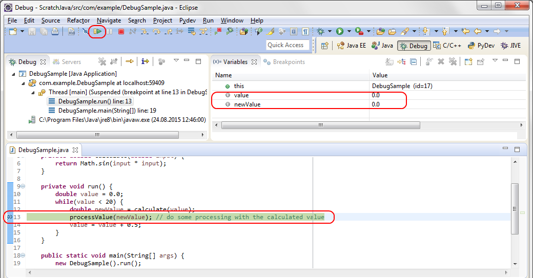
Then, we can launch the application under debugger control and inspect the current contents of the newValue variable in the “Variables” tab:
By pressing “Resume” (or F8), we can watch how the value changes in each iteration of the for-loop.
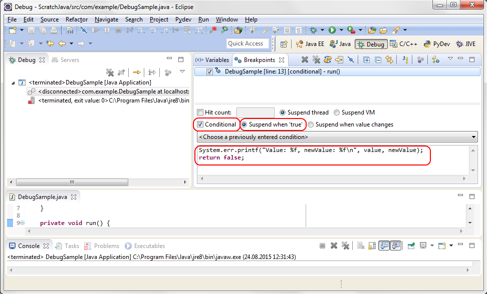
However, this can be tedious, especially if we expect that some issue only occurs after several dozens of iterations. We could add a System.err.println() statement to dump the values to the console, but this requires recompilation and redeployment. In more complex environments this is often not possible (or at least not simple), e.g. when doing remote debugging of a web application. Fortunately, we can define a conditional breakpoint and use a side effect of the breakpoint condition to log variable contents to the console when the breakpoint is hit, while letting the application resume automatically. Simply select the breakpoint in the “Breakpoints” tab and check the “Conditional” flag:
By setting “Suspend when true” (which is the default), we can control through the return value of the condition whether the application should be suspended or resumed automatically. In the text field below, we define the condition (which is really Java code fragment!) which gets executed every time the breakpoint is hit. In our case, the code finally returns “false”, which means that the application is never suspended when the breakpoint is hit, but resumes immediately.
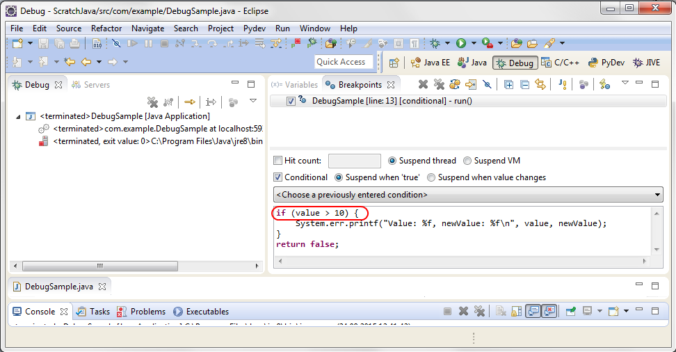
Since the condition is not only a closed expression, but a real Java code fragment including more than one statements, we could also add an if condition to restrict the output to specific value ranges:
In this example, the output only occurs when value is larger than 10.
There is one drawback of this approach when doing remote debugging: The code fragment for the condition runs in the remote VM. Hence, the output from System.err is not shown on the (local) Eclipse console, but whereever the error stream of the remote VM is redirected to. Usually it goes into a log file, so a tail -f on the log file should show the output. Alternatively, if the application is using a logging library, it should be possible to define a logger specifically for debug output and use this logger instead of System.err. Through a corresponding appender, the debug output can then be redirected to wherever it should go.